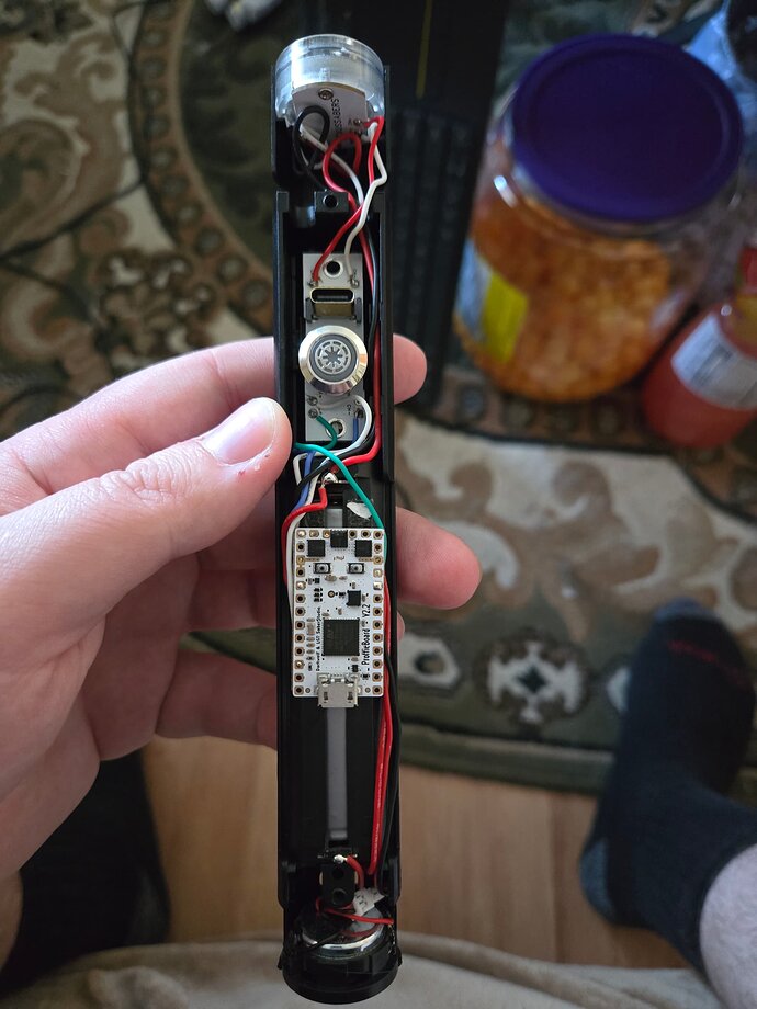
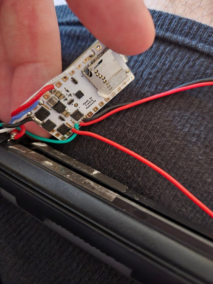
Hello I am trying to make my own lightsaber for my wedding coming up in August and using Crimson Dawn Chassis and 2 Wishiot Tiny 1.5g servo Micro Linear Digital Servo. My plan is for it to have servos for the sword guard to open and close when the sword turns on and off. Based off a another post here I believe I have an understanding on wiring it to the proffie board but coding and programming is where I struggle. When it comes to programming it the servos I have a couple questions. Would the additional code be in the power settings which should require the entire the code that is already on there for all the settings? Or would the servo addition be added to all the blade styles?
Do you have a V2 or a V3 proffieboard?
How do you intend to wire the servo?
Generally speaking, in order to control the servo, we’ll use a style with a SimpleBladePtr. However, ProffieOS normally uses 833Hz PWM signals, and servos need 50Hz signals, so we’ll need to sneak in a call to analogWriteFrequency() somewhere to make it work as intended. I can probably help with that part.
The board is a V2.2.
Wiring I was going to use the method you described in EnRiON post back in May of 2021. Unless there is a different way in this case?
What you mentioned about the the different Hz makes sense and having to sneak in the analogWriteFrequency(). If you could help with that that would be greatly appreciated.
That would be this thread:
Probably the best thing would be if I add a blade type for servos that handles all the underlying stuff, and prints out warnings or something if you try to use it in a way that wouldn’t work.
For your case, how many servos do you need to control?
One complication I just noticed is that TIM15 (which would be ideal for controlling two servos) is used to synchronize the PWM across timers, and that doesn’t work if TIM15 is running at a different frequency.
Yes that was the post I was talking about. My plan is to use two servos one for each side. The sword guard would open and close like Stellan Gios’ Lightsaber except in my case it would be methosaurus horns as the sword guard.
You could hook up the servos in parallel if they are going to be operated at the same time, and the same amount.
Would that be easier to write the code for and get to work?
As stated in the previous thread:
Since TIM2 controls two pads, it would be the natural choice for controlling two servos, but since it is also used for synchronization, that makes things more difficult. There are three choices:
- Drive the two servos in parallel from TIM16 via LED2
- Drive the two servos from TIM1 via LED3 and LED4. (LED6 would also be 50Hz, so it wouldn’t be very useful for driving accent LEDs, but could be used for neopixel power.)
- Modify the code so that synchronization can use some other timer than TIM15.
(1) and (2) are easy
(3) is more work, but still not that difficult.
I think one would work but would that require a splice to the cable connected to data or would we use one of the other data pads?
I think there is some confusion going on here.
The data pads would not be involved at all.
Could you maybe post a wiring diagram?
I’ve attached the images of the wiring for now while I work on a drawing. Looking at it now the wiring of the servos and how the board is wired my brain caught on about my mistake about thinking about the data pads for some reason my apologies.
Seeing how it’s wired now isn’t particularly helpful, what really matters is how the servo(s) are going to be wired.
I’ve checked in some servo support on github.
It’s pretty basic, but adds a new blade type of blade:
ServoBladePtr<bladePowerPin2>()
In some cases it will print out warnings if you try to use it wrong. However, it’s not particularly clever about it, so it’s not a substitute for knowing which timer controls which pad.
There are two things that this doesn’t do yet, which may need to be fixed:
- servos don’t really use the full range of PWM values, and it might be helpful if the ServoBladePtr<> adjusted the input values accordingly. This basically means mapping “black” to 10% PWM and “white” to 90% PWM instead of 0% and 100%. Not sure how much this matters, but servos might get confused if we send them all high or all low signals.
- When using the FETs to generate servo data (with a pullup resistor) the signal will be inverted. For one thing, this means that the left and right will be inverted, but it also means that the start signal for each PWM cycle will move around. I don’t know if servos care about such things though. It may or may not be a problem.
Also, I have not tested any of this yet, so it might not work at all…
About wiring the servos since led 2 and 3 are already used can we use method 2 and just use led 4 or do we need both 3 and 4? That’s my only question about the wiring at this point because ground would go to ground power to power and then just the matter of the signal.
As far as code wise would ServoBladePtr() be instead of also what you mentioned earlier analogWriteFrequency()
Assuming your servo signal line draws less than 13A, just using one LED pad is fine. (That means an almost resoundingly certain “yes”)
You would use the ServoBladePtr instead of, for example, a SimpleBladePtr in your blades array, and yes, Fredrik has made it so that the setup routine for the ServoBladePtr sets the correct frequency.
For a normal type servo, it would be expected that, ignoring the constraints Fredrik noted that the servo ranges are likely a bit less, black will be all the way to one side, and white will be all the way to the other.
Then you just use grays in between should you want some specific angle.
This should work, because LED2/3 don’t need a timer, they are just ON or OFF.
You can also use LED6 to drive the other servo.
If I wire the servos in parallel like you mentioned earlier and connected it to led 4 that should be able to handle the signal correct for both servos or if I’m using led 4 I need to use another led pad as well?
LED4 can drive both in parallel.
Now that we have the wiring figured out. What would be the best way write the code for the servos and where would it be placed?
You’ll need the current version of ProffieOS from the GitHub master, (Code->Download Zip) then in your config file, add a ServoBladePtr w/ the pin you want to use to control the servo. So in your case it sounds like it should be: ServoBladePtr<bladePowerPin4>()
Then, you add a new bladestyle to each preset. You should only use greyscale color values (i.e. red, white and blue values are always equal), and whenever the color is black the servo should move to one side, and when white it should move to the other.
You’ll want to use the Style Editor to create a bladestyle that works for your use case. For example, you could do something like this:
StylePtr<Layers<Rgb<240, 240, 240>, InOutTrL<TrInstant, TrInstant, Rgb<20, 20, 20>>>>()
as per Fredrik’s suggestions, I’ve not used pure black or white, but slightly off-black and off-white
Which would have the servo on one side when the saber is off, and on the other side when the saber is on (in theory).
Here’s a minimum config to show how this would work:
#ifdef CONFIG_TOP
#include "proffieboard_config.h"
const unsigned int maxLedsPerStrip = 144;
#define ENABLE_AUDIO
#define ENABLE_WS2811
#define ENABLE_SD
#define ENABLE_MOTION
#define SHARED_POWER_PINS
#define MOTION_TIMEOUT 15 * 60 * 1000
#define PLI_OFF_TIME 2 * 60 * 1000
#define IDLE_OFF_TIME 10 * 60 * 1000
#define CLASH_THRESHOLD_G 3.000000
#define ORIENTATION ORIENTATION_FETS_TOWARDS_BLADE
#define VOLUME 1500
#define NUM_BUTTONS 2
#define NUM_BLADES 2
#endif

#ifdef CONFIG_PRESETS
Preset blade_in[] = {
    { "FontDirectory", "",
        StylePtr<Black>(), // Main Blade Style
        StylePtr<Layers<Rgb<240, 240, 240>, InOutTrL<TrInstant, TrInstant, Rgb<20, 20, 20>>>>(),
        "example\npreset"
    }
};
BladeConfig blades[] = {
	{ 0,
		WS281XBladePtr<144, bladePin, Color8::GRB, PowerPINS<bladePowerPin2, bladePowerPin3>>(),
        ServoBladePtr<bladePowerPin4>(),
		CONFIGARRAY(blade_in), "blade_in"
	}
};
#endif
Disclaimer: This was freehanded, and there may be inaccuracies, but even so, this should provide a good idea of how to set this up

