So I bought an Aouye soldering station, but the software is kind of dumb. It always starts with the default temperature and air flow settings, which is really super annoying. In addition, I think it should be reducing the air flow when working on heating up to heat up faster. (It has a cooldown mode where the air runs faster to cool down, but it doesn’t have a heat-up mode to heat up faster…)
Anyways, instead of just sending it back, I decided to open it up to see what I can do about it. Here’s what I found:
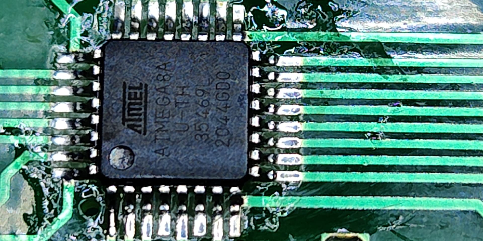
It’s a little hard to read, but it’s an Microchip Atmel Atmega8A chip. The PCB is already set up for programming, I just needed to add some header pins. Unfortunately, the lock bits have been configured to prevent people from download the program that is on the chip, which means I can’t make a backup of the program that is on there.
So instead of making a backup, I’m just buying another Atmega8A chip. That way I can just replace the one that’s on the PCB with a different one and leave this one programmed the way it is.
While I wait for my new chips, I’ll start working on the program. It should be relatively simple. The board has 7 anode connections to the display (one per segment) and 8 cathode connections (one per digiit). There are 6 buttons, one of which is latching, and then there are 4 pins that actually hook up to the rest of the soldering station. I suspect that these are configured as:
- Thermistor input (for reading the temperature)
- heat control (probably through PWM)
- air control (probably also PWM)
- 50/60hz input for timing.
I need to measure these and make sure they work the way I think they do, and also which is which.
If I could find a cheap air-flow sensor, I would see if I could replace the 50/60hz input with an air flow input, but I that seems hard to find.
3 Likes
Nice! You could probably mess with some PID to get even more accurate/stable temperature output. It might be a good idea to create a output curve by measuring temperature droop for higher airflow. You’d need an external thermocouple to calibate it the first time.
…all this in the spirit of doing something rather unnecessary for the heck of it. 
1 Like
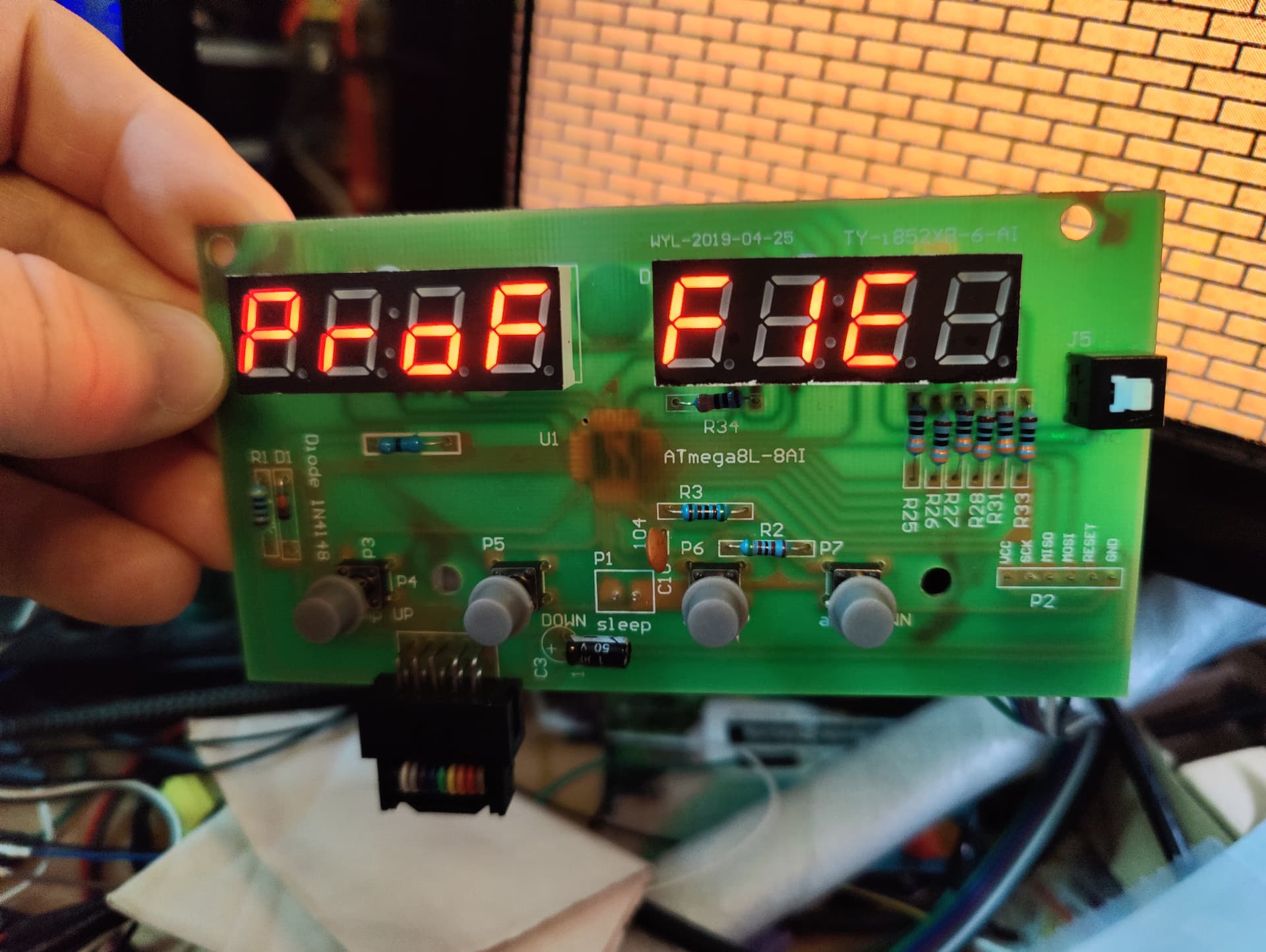
Got my processors today, so I figured it’s time I did some analysis on what control signals coming in/out of the control board looks like. Here is what I found.
There is a 10-pin connector between the control board and the power board.
Here is what each pin does (seen from the front)
|
|
|
|
|
| 5v |
pump control |
NC |
NC |
GND |
| 5v |
heat control |
thermocouple |
120Hz AC sense |
GND |
- The pump control is a 120Hz PWM signal, synchronized with AC power.
- NC means “not connected”
- the heat control is active low, but only changes when the AC sense is low. This makes sense since FETs and simlar circuits are the least efficient when switching. When on or off, they the most efficient. (Meaning that the AC voltage is near zero.) The output pattern seems a bit chaotic. At full tilt, it turns on for 14 120-hz cycles and then off for two. When maintaining temperature, it turns on/off for a couple of cycles, then turns off for a few seconds before turning on again.
- The thermocouple input is amplified already, so it’s 0.54 volts at 100C and 1.94 volts at 400C, and seems very close to linear in between. (I have not calibrated this yet, it’s just what it says on the display.)
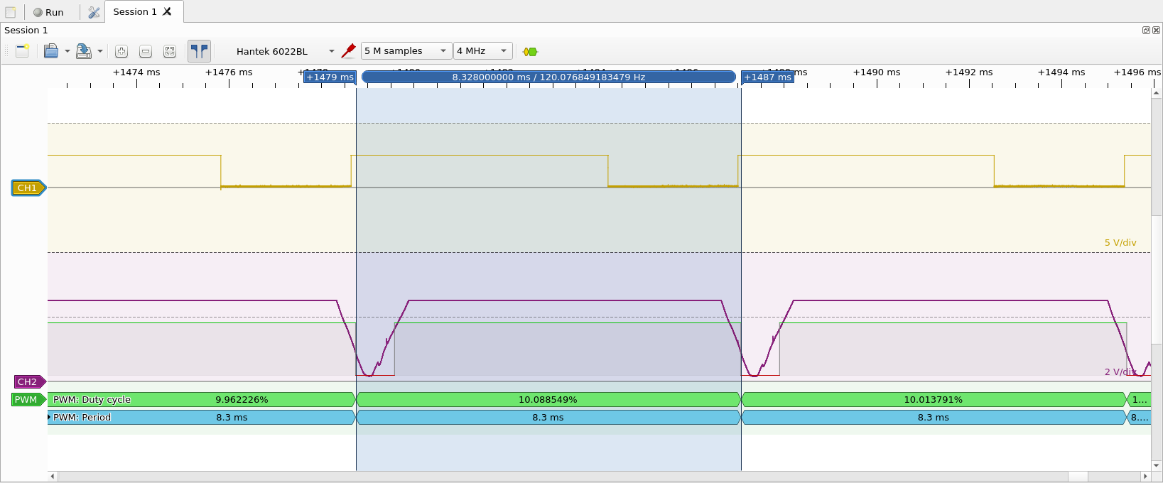
The synchronization between the AC sense and the pump control looks like this:
Yellow line is the pump PWM (active low) and the purple line is the AC sense input.
3 Likes
a full custom job I see.
like the extra touch!
I’m a little annoyed with whoever designed this PCB. Neither the pump control, nor the heat control are routed to PWM-capable pins. Also, the AC sense is not routed to an interrupt-capable pin.
It is possible to get an interrupt from the AC sense by using the on-chip comparator, but you can’t use the ADC at the same time. So either I have to poll the AC sense, sync it to a timer, or timeshare the ADC mux. All of these options makes the programming more complicated that it needs to be. 
Assuming I sync the pump PWM to 120Hz, like the original firmware did, synchronization precision has to be fairly good, otherwise the power levels will fluctuate. (Since the power is likely going to be increasing at the time that I cut it off.)
Also, the last digit on the display is not controllable at all. Seems they ran out of pins, however I’m reasonably sure that could have been worked around with a little charlieplexing.
2 Likes
Just in case there is any confusion about how dangerous it can be to re-program your soldering station:

While I was trying to figure out something, I accidentally left the heater on. After a little while, I heard a small pop, and a small blue flame appeared from where the hot air is supposed to come out. After letting the whole thing cool off, I took the handle apart, and this is what I found…
These heating elements only cost $15 to replace. Luckily I’m not stupid enough to leave the handle on my desk or somewhere where the heat could have done additional damage, but still…
1 Like
Yikes, glad nothing worse happened!
1 Like
Wonder if I could use one of these to get a feedback-loop for the air flow…
1 Like
Did you ever do anymore with this project?
How did you do the custom startup text?
Did you ever figure out a way to chamge the default start temp and air flow?
Not really. Once I bought on of these, I basically stopped working on this.
I replaced the controller on the board with one that I had programmed myself.
(And traced some traces to figure out where they go.)
Not really how it worked, as I was replacing the entire program on the controller.
I had some basic stuff going, but the PIDs needed adjusting and it wasn’t working particularly well when I left it…
1 Like