Installing these momentary switches from korbanth on a proffie v3 board. I’d like to have the leds on them work but can’t wrap my mind around how to wire them to the board. Looks like theres a positive, negative, data, switch, and switch ground pad on them. Obviously I know the switch goes to the button pad on the board and where grounds go. But can’t figure out where the positive and data go and where to put the resistor.
The LED wiring would be just like any other blade. Positive from the battery, negative to an LED pad, data to a data pad.
Of course you have options of how you want to wire them. Together in parallel as one blade, in series as one blade of 2 Pixels, or two separate blades either on separate data pads or as a sub blade on one data pad. It’s up to you and your wiring choice.
How would I wire them together to both do the same thing? Just put both data lines to the same data pad on the board?
I recommend wiring them in series. You can still program them to do the same thing if you want to. If you wire them in parallel, you will need to re-do the wiring if you ever want them to do different things.
*If I may ask since I kinda see a lesson here?
@profezzorn For clarity you mean wire in parallel as far as the lights themselves and whichever switch common wire correct? Just so the OP has the info.
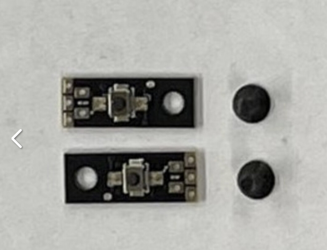
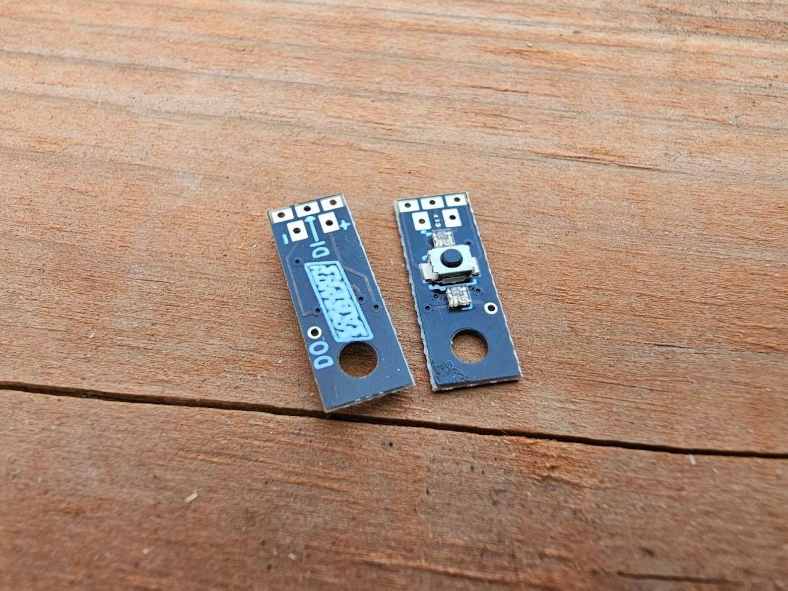
@Ryan_Mertus first of all Welcome to The Crucible. Second here’s the backside of the switches, (image via Etsy) which will give some more clarity as to how to wire things up. Your next step is to use the wiring diagram resource that’s on this page to lay things out accordingly.
I mean wire DO of one light to DI on the other light and use the same LED pad for +/-. Then use subblade to make it two blades. If you want the them to light up at the same time, then just use the same style twice in each preset.
Ok so just to clarify from what I’m seeing in the manual. I can take the negatives from both led switches and run those to the same led pad on the board. Both positives go to the battery, and both data lines to the same data pad with a resistor? I don’t need them to do separate things I want them to match. Not sure I understand the difference between wiring them parallel vs in series.
Series you run from board to data in (DI) on first switch and the from data out (DO) on that first switch to data in (DI) on the second switch.
This lets you run them with the same style or later you can set them as separate sub blades if later you want to have different effects.
Parallel you run 2 wires from the 1 board data pin to the two switches data in pads. You only have the option of running the same effect on them then. If you change your mind you’d need to reword it
Ok that clears it up. Thanks! I will be running them in series since that seams to be the simplest wiring for the chassis I’m using.