I’ve designed a 3D printed adapter for the Proffie Breakoutboard. I’ve designed a bed with two levers that are secured by a ring o the top. If you have access to a 3D printer (mine is resine), you can get this elegant solution. This way you need a single board, rather than two.
The only problem is that one lever prevents connecting an USB cable while the board is pressed. If anybody else is intereted, I can widen the design a bit so a cable can fit within the arms.
1 Like
Interesting design. Not being able to connect the USB is pretty much a fatal flaw though. And it looks like accessing the buttons is fairly difficult too?
What if you rotate the design 90deg, so the arms close over the long edges of the board instead? (and integrate plungers that can push the BOOT and RESET buttons 
Maybe a solid printed ring would suffice to slide smoothly on the top post instead of a “grabby” o-ring?
2 Likes
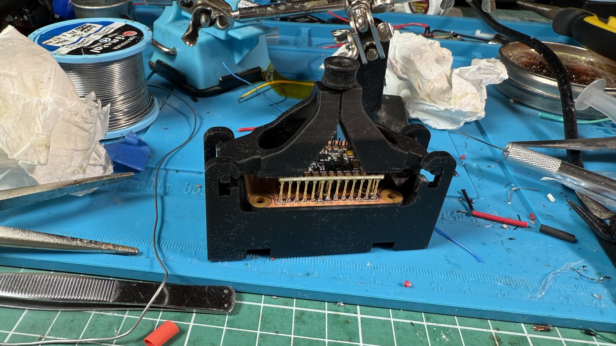
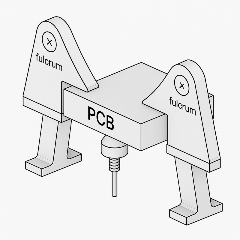
I’ve designed this new version. It does pivot on the other direction, the USB access is clear, has holes for plungers for Boot and Reset (which I’ve labeled) and now uses a triangular passthrough to keep it. It’s a triangle because it simplifies printing.
If it seems good, I will add the triangular pin and the plunger and send the STLs. I won’t be close to my printer for about 10 days.
2 Likes
Looking good! Fun, right?
Looks pretty good. I might “steal” some of your ideas. If I may ?
1 Like
I like it.
I have an idea for a possible improvement…
The idea is to skip the triangular pin.
Instead, there would be an edge on the rotating piece that holds the board in place…
Hmm this might need some sort of drawing…

Click on it to see the whole thing. This viewing the rotating profile from the side, and there would be another thing like this on the other side of the board.
The idea is that the PCB springs would hold the pcb in a stable groove in the rotating parts, and you would have to push the board down slightly to rotate the rotating parts out of the way. (Either up, which would be clockwise in the drawing, or down.). If the rotating parts are balanced the right way, then they will automatically fall into place when you put the board in, but require a manual operation to get the board out. It may even be possible to make it toggle so that both in and out can be done by just pushing the board down, although I’m not sure how to do that…
Yep, more or less anyways.
It could also rotate the other way.
The shape is just a placeholder to explain the principle.
The final shape could be anything that has a similar function.
1 Like
I think I get the gist of it. I will try to design a cam where you just insert the board with pressure but have to push the board down and pinch the levers to release them. But you lose the Boot/Reset buttons and have to do some force. Those 33 pins make some surprising force up. Nothing I don’t find easy, but for women or teenagers it might not be that simple.
I designed the levers so high to get a lot of leverage for a smooth movement. So I’ve been thinking and I can make a D-ring type lock on the top of my current design, too.
Since I will be away from my equipment for a couple of weeks, I will design the D-ring variation and then experiment with the overhead levers concept.
Please! I’ve been an opensouce guy since the early 90s. Ideas are for sharing. Just show us you designs so we can all learn and thrive.
1 Like
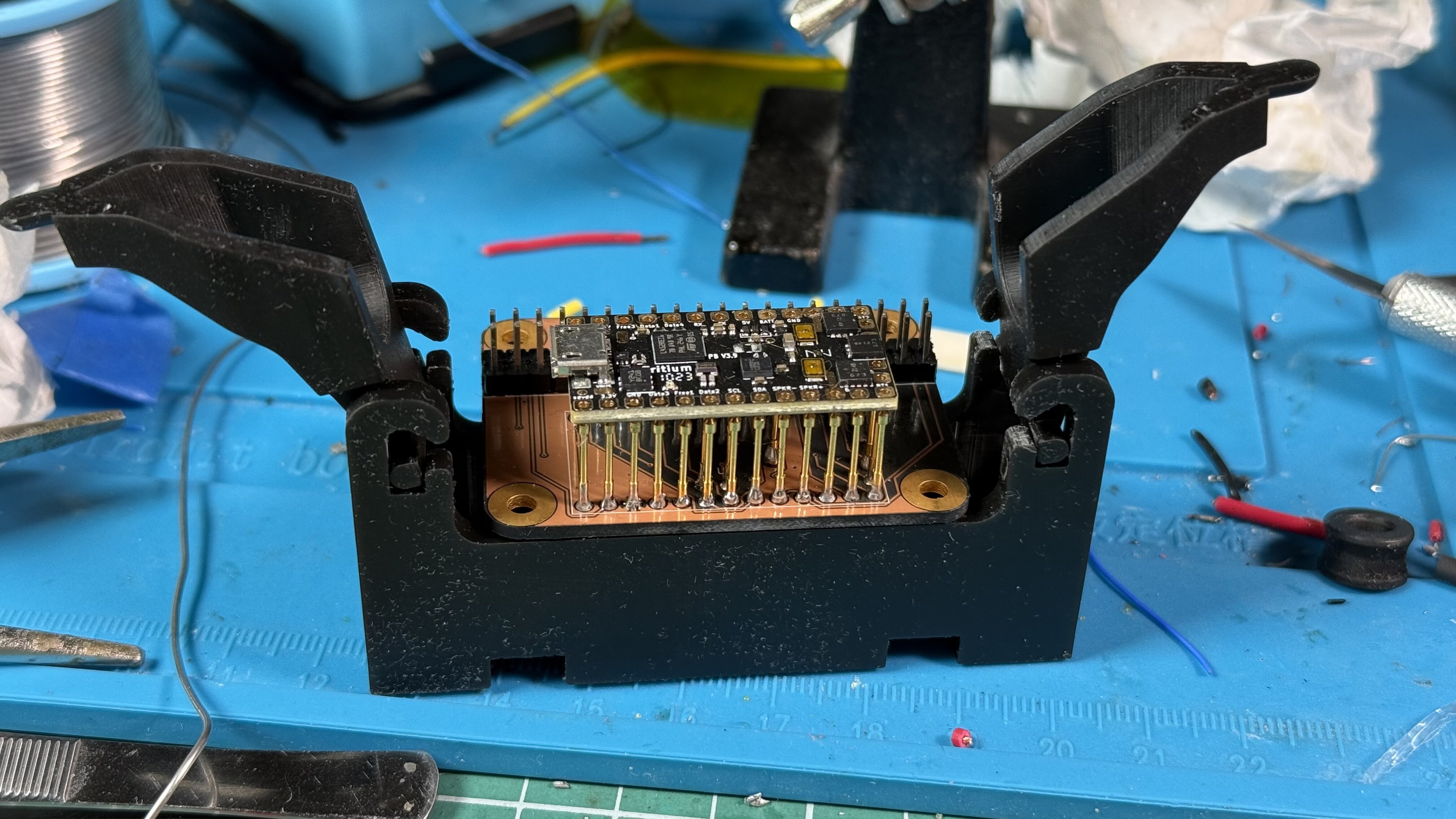
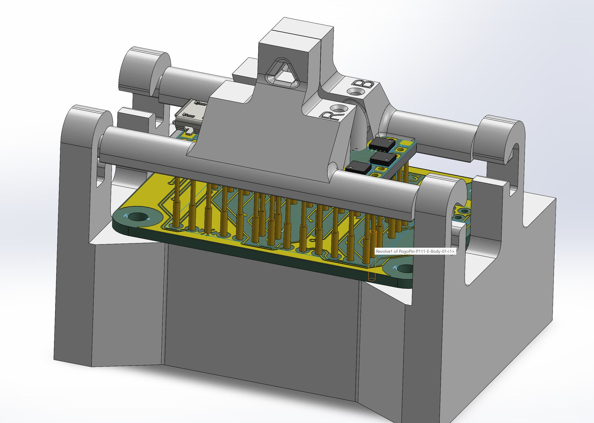
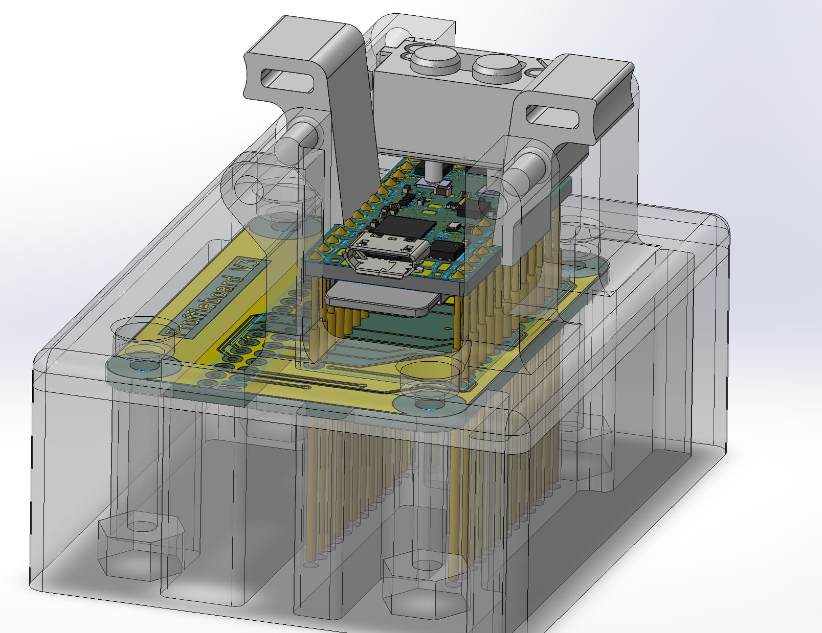
New version. It’s been made very difficult due to the distance between the board and the dual 20 pin connector. @profezzorn , if the next breakout board you design allows for it, putting the screw holes between the board and the pin connector, or leaving about 10mm of clearance, would help a lot on designing an easier locking mechanism. At least for someone with my limited design skills. This is not a critique, since I’m deeply grateful for all you did and do. It’s just a suggestion for the future.
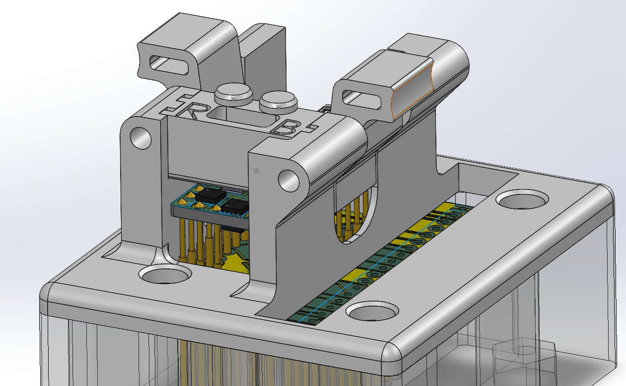
This is the beta version. I still have to print it and test it. The pinout side is very thin and had to put some reinforcements on the extremes. And yet I’m not sure they will be able to resist the forces nor if a connector can actually be plugged. Regrettably, I only procured a male connector without a border, so I don’t know the actual limits. Had to work from the datasheets.
The plunger module is a drop in add on, and has to be put each time you swap a board. I haven’t been able to solve for an integrated solution like in the previous version.
The only thing I will change before printing is I will make the axle of the levers a separated piece. This will simplify printing and add some strength to the supports. Other than that, I’m out of ideas. If anybody can help me with ideas or modifications, that would be greatly appreciated.
Let us know how it works out.
If it doesn’t work, I would suggest moving the posts that hold everything further out, and then use a threaded rod (2-3mm diameter) for the pins/axis.