A Neopixel wiring question with blade id

Hi, while working through my increasingly complex wiring diagram and reading through the documentation, I hit a snag on this line about BLADE_ID: " IMPORTANT NOTE - BladeID requires a direct, uninterrupted connection from the board’s data pin to the main blade (usually the center pin on the hilt-side of the main blade PCB). Therefore using SubBlades with neopixel accents, crystal chamber, or NPXL LED PCBs in series with the main blade won’t work…"

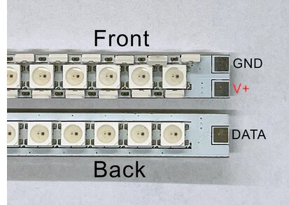
I am planning to use a Shtokworks hilt PCB, which has built-in LEDs and am choosing between the V3 and V4 wiring options from their documentation (


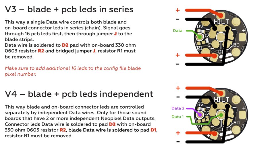
), due to a thin neck constraint on wiring, i was going to use the V3 wiring–blade + pcb leds in series, and use subblades to handle the LEDs in the PCB (even though they would not be visible when the blade was installed). On the blade side PCB, I was planning to use a 51k 0603 0.1w resistor for blade id.

I was also planning to use this chassis in other hilts–so I thought I could add a 20k ohm resistor on the hilt side for this specific hilt (1/2W), between Data 1 and LED 2+3. My understanding was that these resistors would be additive so I could trigger blade configuration specific to the blade/hilt combinations: 50k for the quad blade, 70k for the quad blade and hilt chamber, 20k for this hilt with a different blade.

None of this is wired yet–so I cannot test anything–but I thought I should ask before I start soldering… here is my draft blade config:

BladeConfig blades[] = { { 1, WS281XBladePtr<144, bladePin, Color8: - Pastebin.com

Here is my wiring diagram for this section of the hilt/blade:

To circle back to my question: can I wire the hilt pcb so the built-in LEDs are in series and still use Blade id? If not, would it work with the V4 wiring option–blade and PCB LEDs are independent (they still have shared power pins). Will a resistor on the hilt side stack? What about splitting the main blade into 4 subblades–can that be done at all with blade-id?

Oh, and one crazy question to throw in for merriment–can the same pixels be assigned to multiple blades in the bladeconfig? I was thinking it could be useful to address the blade as a whole for some styles while others would only affect a section/side of the blade.

thanks in advance–and happy holidays.

Answers…

Not additive, since they are hooked up in parallel.
The formula is R_{measured} = \frac{1}{1 / R_{hilt} + 1 / R_{blade}}
Of course, none of this matters if you’re using the snapshot blade ID, since the values will be kind of random in that case.

More details here: All you need to know about electronics

no

yes

what? no, what would that even do?

Addressing one “side” of the blade is only possible if you have a zig-zag blade.

Now for some options…

  1. V4 will require one more wire, however, there are lots of very thin wires available, and data wires do not need to be thick. 30-awg PTFE wires are highly recommended. More information about wires here: The Wiring Selection
  2. If you can’t do V4, you could have the PCB and the blade wired in parallel, this works reasonably well since you usually can’t see the blade and the PCB at the same time anyways, so you can use blade detect (or blade id) to select what to show.
  3. You could potentially drop the blade detect pin and just rely on blade ID. We have code that can poll blade ID and detect when a blade is added/removed. However, it’s not quite as reliable as blade detect.

I would venture to say that if you do V2 and wire them in parallel as @profezzorn said, there’s no drawback to it compared to using SubBlade since in the “blade in” state you can set it to the right number of pixels for the main blade and style it normally, and in the “blade out” state, you can reduce the pixel count to match the PCB and then style accordingly. This parallel connection counts as a “a direct, uninterrupted connection from the board’s data pin to the main blade” and should allow for BladeID to work. It has in my experience.
I highly recommend you use Bridged Pullup Blade ID class as it gives much more usable values for Blade ID. I don’t think you mentioned which version Proffieboard you’re working with, but that means nothing additional to you if it’s a v3 board as that’s the default internal configuration.
If you have a V2.2 board, you can bridge the adjacent TX pad and add define BLADE_ID_CLASS BridgedPullupBladeID<bladeIdentifyPin, 9 to your config.

I am using a proffieboard V3.9.

To make disassembly possible, I have multiple connection points–and the issue with the neck is connector size, not wire width… but your suggestion to use another data pin instead of blade detect solves that problem. I really don’t plan to use blade detect, which gets me down to 4 wires instead of 5, and I can fit a 4 pin JST through the neck if I trim it a little. So that part of my “question/problem” answered/solved.

The Tritium pixel strip is a cross between a zig-zag blade and the KR Sabers pixel strip, (image below) which I believe has 477 independent pixels facing in four directions (
image
)–but I believe they are wired in sequence from base to tip, thus the subbladewithstride using a step of 4, and no need to reverse the directions like with a zig-zag blade. I planned to use subblades to access all the blade styles that work with quad zig-zag blades.

if I use the V4 wiring, putting the LEDs on the PCB on their own data pin… can I use blade-id and subbladewithstride to create subblades for each “side” of the main blade as shown in the pastebin bladeconfig? I just want to control the blade config for a standard blade (144 pixels) and a tritium blade (477 pixels) with independent pixels facing in 4 directions (like a quad zig-zag blade). ( BladeConfig blades[] = { { 1, WS281XBladePtr<144, bladePin, Color8: - Pastebin.com)

The idea behind mapping pixels to more than one subblade comes from my experience in data processing (e.g. pass a pointer to a subset to a search routine rather than a pointer to the full collection). With a pointer to the entire blade, a single call can turn the blade Cyan, with a specific flicker pattern but I could also use the subblade pointers for the styles that benefit from a quad-blade design. Your question “why do that” has pushed me to reframe how I think proffieOS works–rather than calls to a style with a blade-pointer, style pointers are assigned to each blade and called continuously in series for each blade. Multiple blades sharing pixels would constantly overwrite the prior instructions and not behave meaningfully. Is my reframed perception correct? I could still see benefit for events like clash–which could be drawn using a pointer to a subset of a full blade… but that’s something to ponder another day.

For my question about series vs parallel resistors–thank you, I think I understand now. For the resistors to stack, the first one would need to be in-line on the wire from data pin 1, rather than shunted to LED 2/3–but I can see where that could be problematic–it was a wish-list item and I have figured out a solution.

again, thanks,
Js

I solved this problem by using two connectors instead of one, as I can feed one through at a time.

Yes. The only potential problem is to make sure that the saber detects when a blade is inserted/removed. Doing this without blade detect is relatively new and not widely tested yet, but it should work.

No, all configurations must have the same number of blades.
You’ll want some dummy blades to fill out the entries that don’t matter. Something like SimpleBlade<NoLED, NoLed, NoLed, NoLed, -1, -1, -1, -1>().

This is exactly what subblade does.

This conclusion is essentially correct. The description before that sounds weird to me, but I think you have it right.

1 Like