Hi! I’m doing an install on a 89Sabers OWK1. I wanted to design the chassis as well as perform the install. I will later show the process of actually installing. But for now I would like to focus on the chassis design.
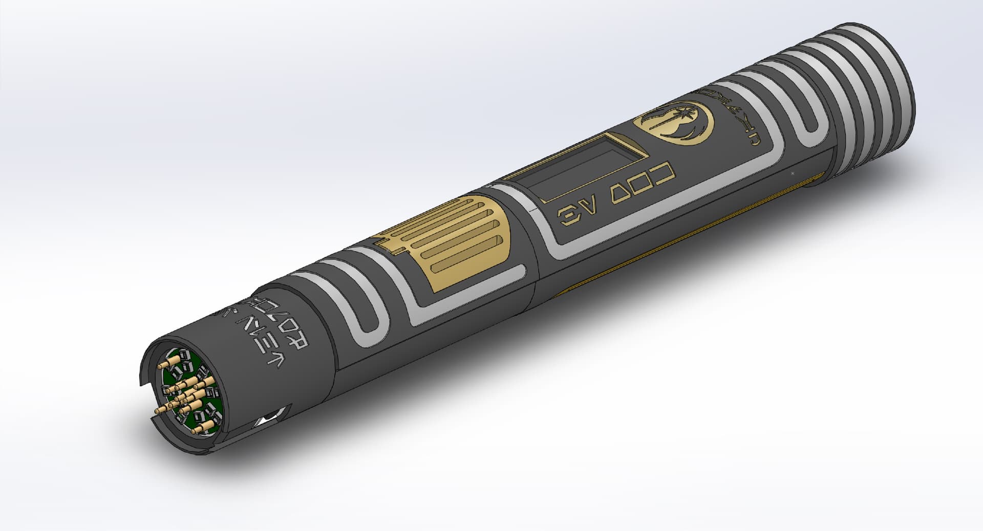
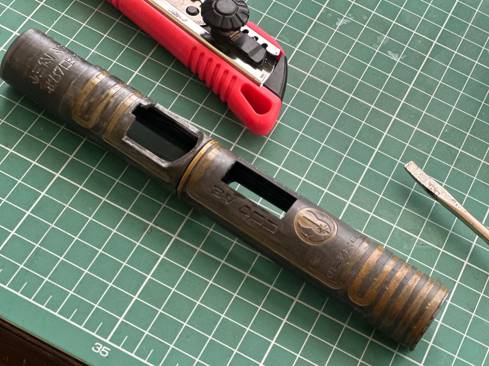
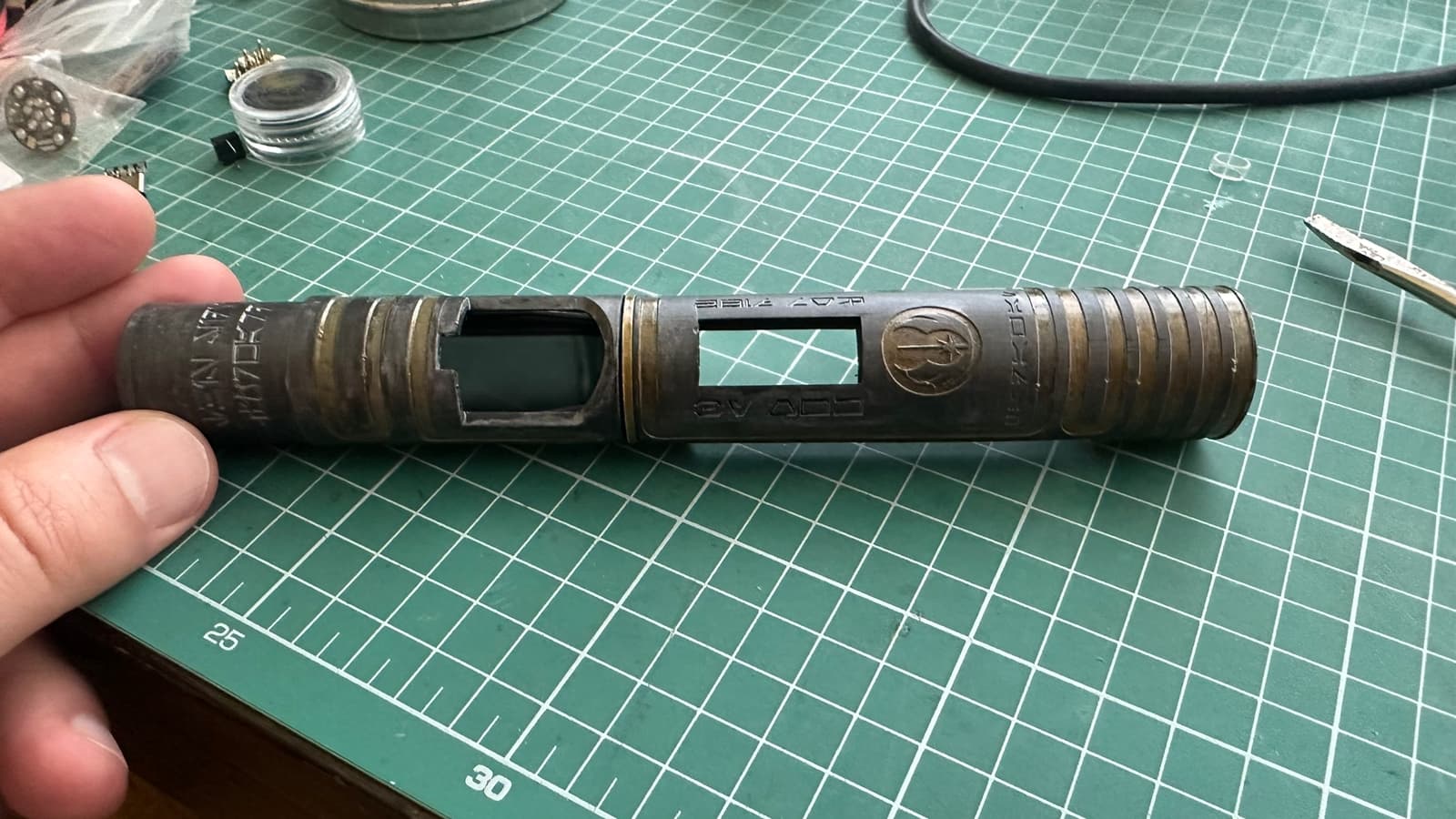
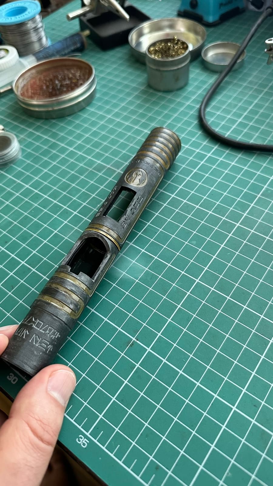
The hilt is already kinda narrow (26.35mm ID), but it has an internal plate for decorative purposes on the handle. Which further narrows the diameter. Thus, the chassis has a different diameter on the upper and lower half. Is that the reason I could only decorate one side.
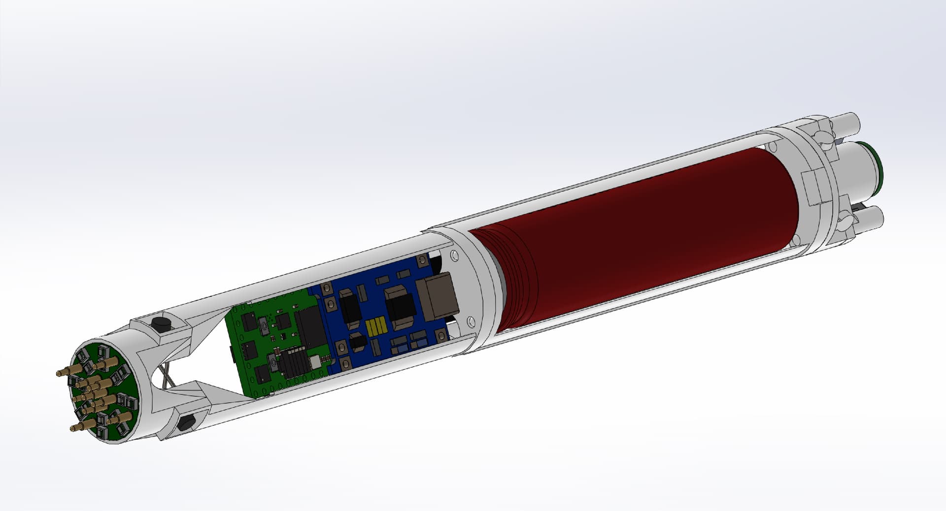
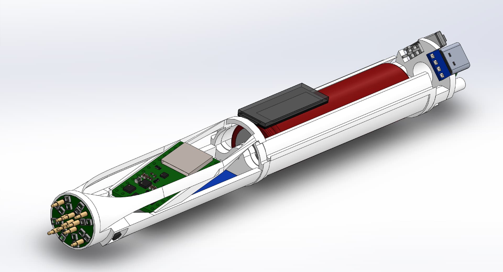
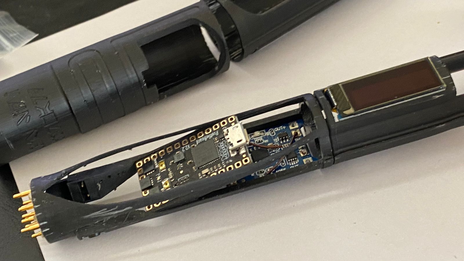
The chassis is design to have an internal chassis which makes it easy for installation, and then it slides into an external skin. The design might seem weird, but my printer is a Creality Halot One and I just can’t get good radial tolerances unless I print the parts upwards. And since I can only print 160mm tall, I decided to divide it into parts which also reduced the printing time.
I’m far from a master chassis, but I’ve already learned to fit everything, make space and trenches for routing cable, give easy access to the installer, and make it practical for the user.
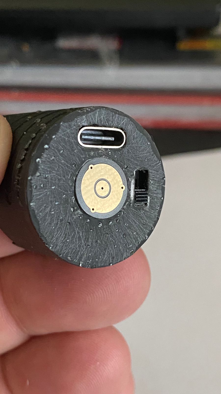
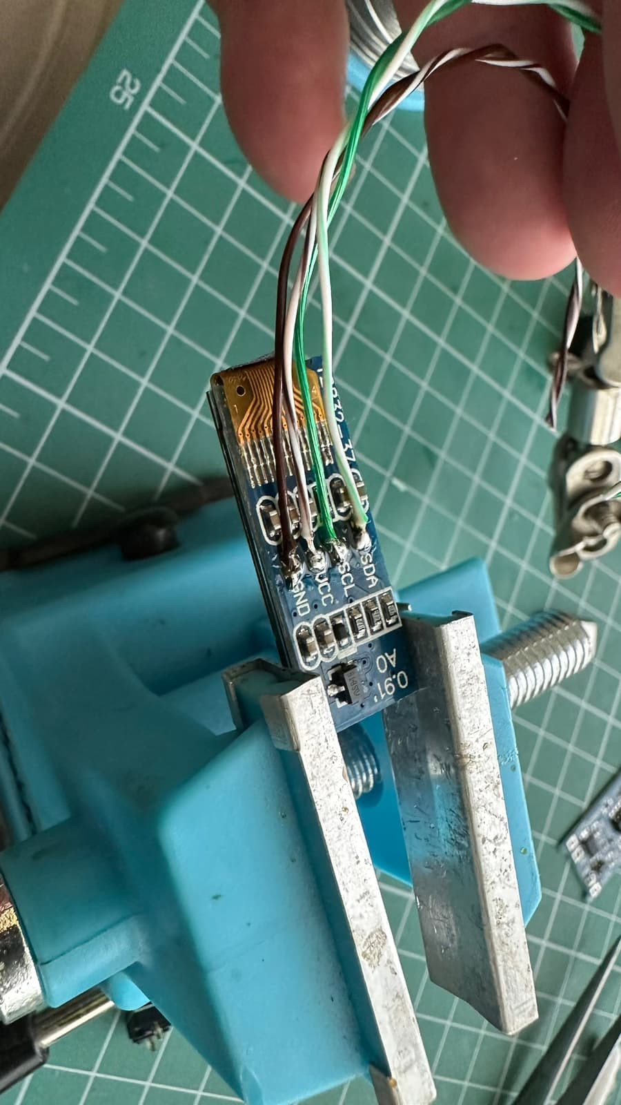
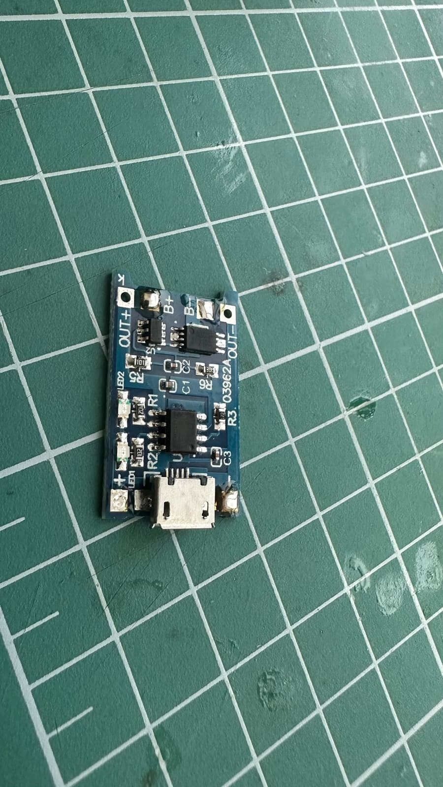
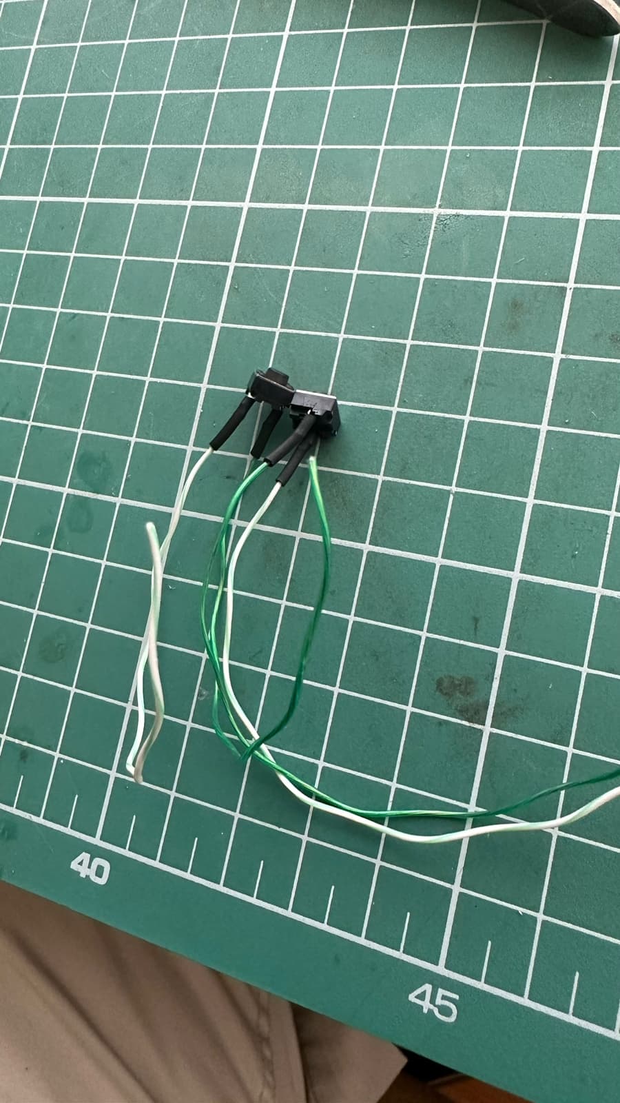
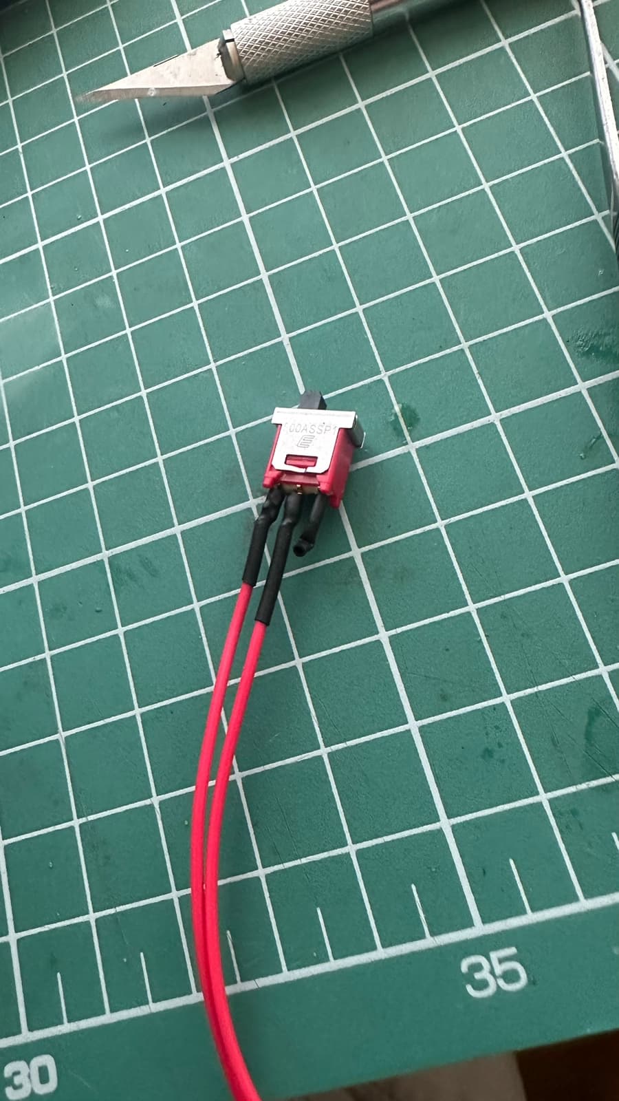
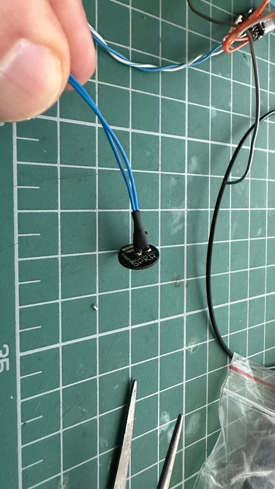
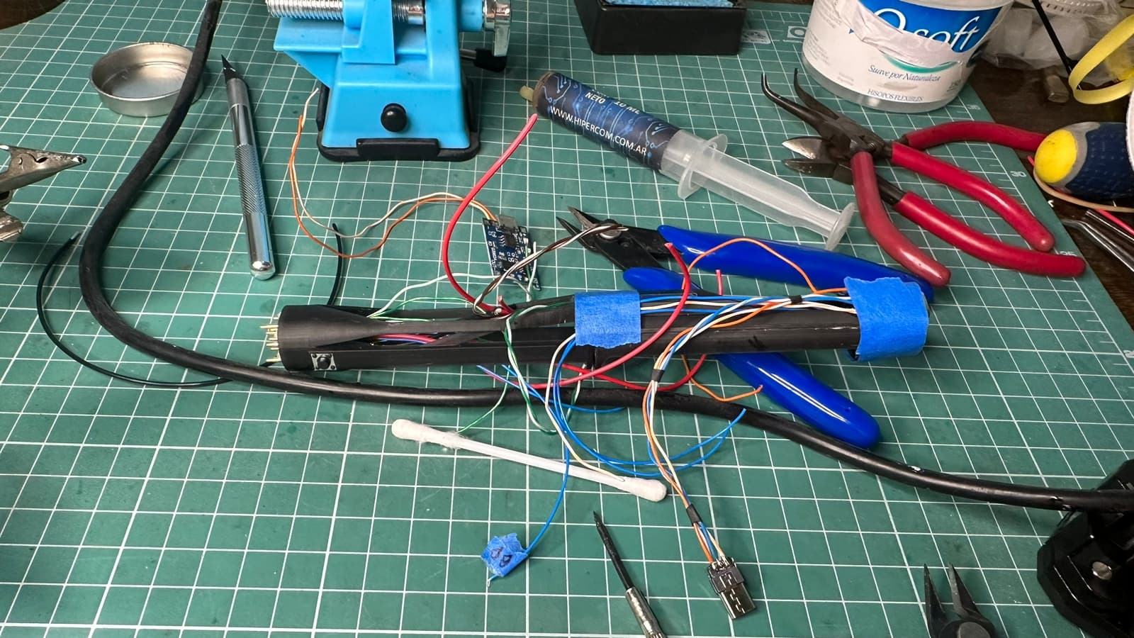
The speaker is installed on the pommel, so I used a Shtock connector, and put there an USB-C for programming and power as well as an on/off switch. The particular hilt allows to rotate a cover that would allow access to part of the chassis, as well as plunger switches which allows for easily slide in design.
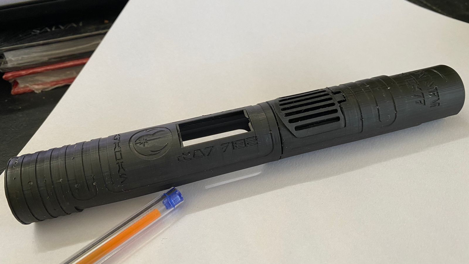
I’ve already printed a prototype and corrected printing and dimensions. But I guess I will have to print a further two prototypes. I guess I’m at a moment where I would really appreciate any piece of advice from more experienced installers.
Ok, after struggling with the print side, this is my first beta prototype. I have to add some margin to the OLED, but the rest is fitting great. I think that for a Padawan level chassis, it is starting to look great. The ease of installation is high given the level of features, while the aesthetics are very acceptable for the level of sophistication from a padawan.
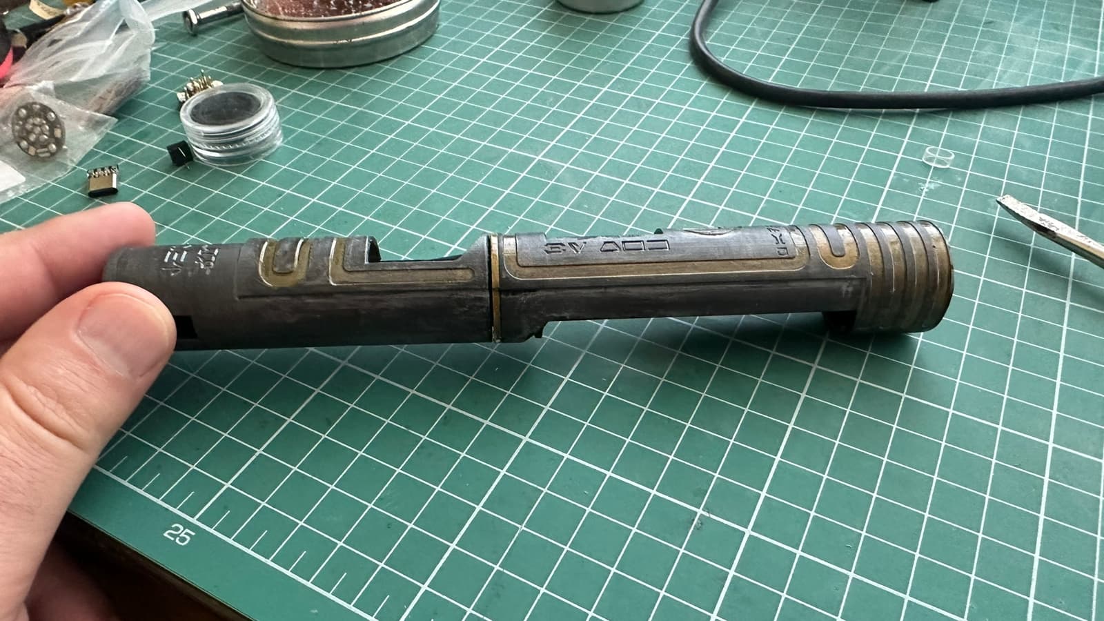
Since this prototype has done its part, I guess I should actually practice painting the logo, text and lines for a final prototype status. Regrettably, I don’t think painting the whole thing would resist the markings from friction with the hilt. I guess I should try, though.
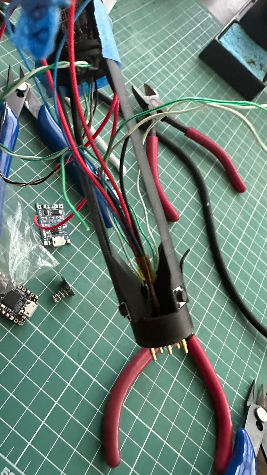
I still haven’t glued things, but I have excellent access to all boards and contacts. And while it might not look clear at first, on the side of OLED those are a trench on each side where I can route a lot of cables very neatly. I think I will use this as the basis for most of my future designs.
After months of not doing the necessary changes in my house to enable the constant use of the 3D printer, I’ve go back to this project. I did a new print and did some light painting. It actually looks better in person than the pictures.
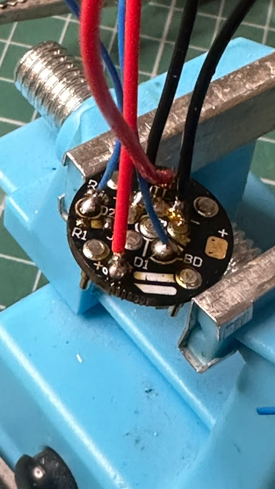
@profezzorn I’ve just read that BladeID won’t work with illuminated PCB in series (Duh! Why I didn’t think of that?). I’m using Shtok’s excellent V3. In the V4 configuration, when they are used with separate lines for accents and blade, the accents have a 330 Ohm resistor. Can I not use a 470 Ohm Resistor on Data 2 and use that to drive the accents? In other words, do the 330 Ohm resistor on the PCB can save me from having to add a 470 Ohm resistor to the Data 2 line?
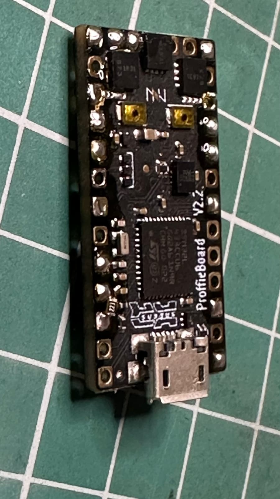
You should not need to add another resistor.
For Data1, the one on the proffieboard is all you need.
For Data2, the one on the pogo pin PCB is all you need.
You might want some resistors in the blade though, but that’s different.