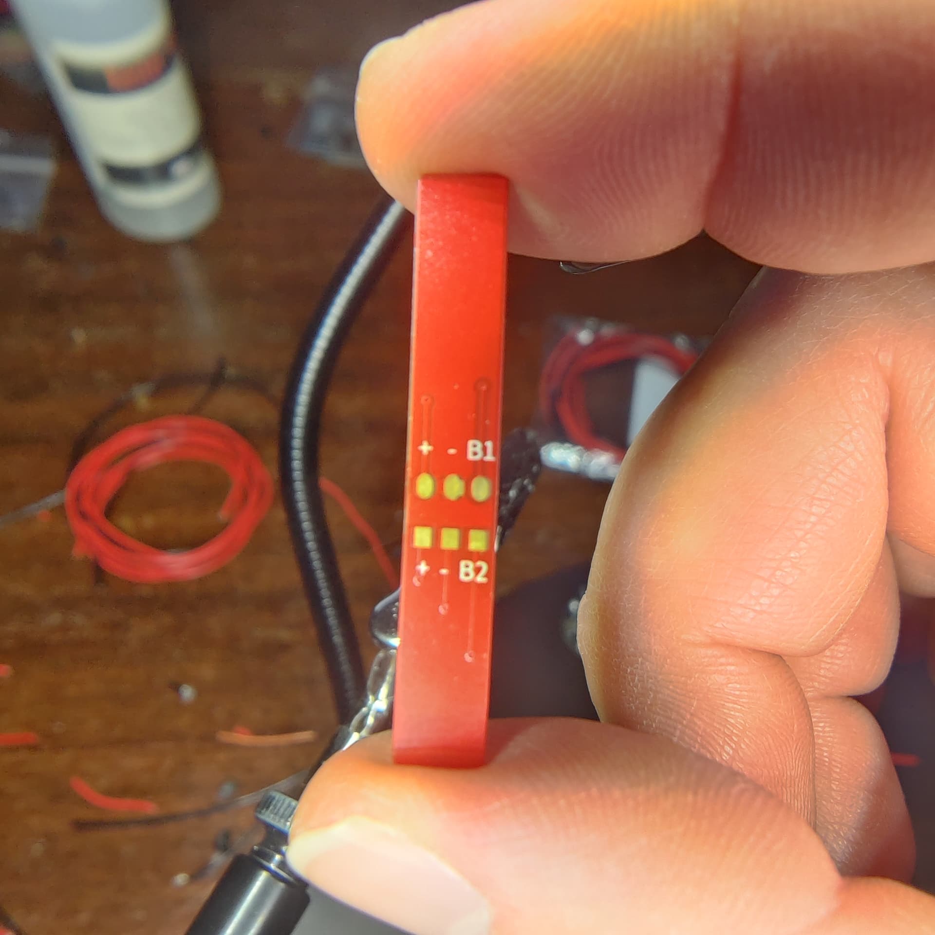
I just got the 89Sabers Kylo Ren hilt and the button PCB has button1, button2, 2 positives, and 2 negatives.
I haven’t worked on a button PCB that has positives yet and I’m unsure how to hook it up.
Any help is much appreciated!
I just got the 89Sabers Kylo Ren hilt and the button PCB has button1, button2, 2 positives, and 2 negatives.
I haven’t worked on a button PCB that has positives yet and I’m unsure how to hook it up.
Any help is much appreciated!
Presumably the + and - go to LEDs?
Generally, when you get a PCB from someone, they should provide instructions for how to use it.
It does have LEDs.
Obviously the button 1 and 2 go to their respective pads but I’m not sure about the positive and negative.
Would the negative have to be driven by the MOSFETs and would the positive be hooked up to board positive or to the 3.3v pad?
Short answer is yes. You could probably drive it off the battery, but you would need an additional resistor. I have an 89sabers sidious i am working on and i think they have the same led button pcb. It is pre resistored.
I would try to reachbiut tothe seller and ask the question.
You may be able to use the 3.3v pad.
You may be able to use the Free* pads.
It depends on how much voltage the LEDs want, and if they have resistors or not already. (And if they have resistors, what voltage are they resistored for?)
89sabers should know what voltage the +/- pads are mean to receive.
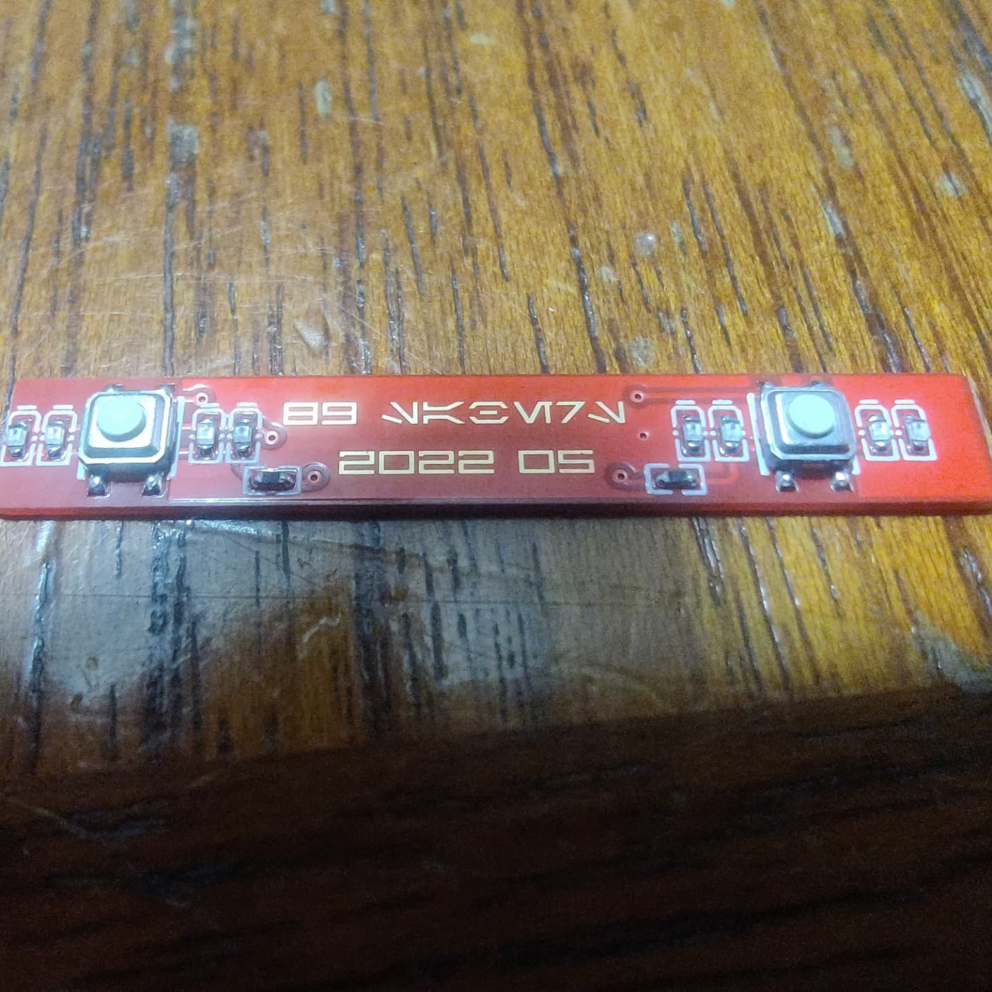
This is a picture of the PCB.
The resistors aren’t labeled and there is 1 resistor per and 4 LEDs per button.
You can measure the resistors, and you can also measure the forward voltage of the LEDs. (Assuming your multimeter has that function.)
Have you tried reaching out to 89sabers?
I bought it from a reseller (Saberbay) so I’m not sure if 89sabers will respond to me cause I don’t have an order number or anything.
Saberbay will absolutely help you out. Give them an email.
He worked with 89 and me when I ordered a hilt and it was missing some parts.
How do you do this?
Your multimeter will have a special mode, called VF, or it may just have a diode symbol. Switch to that, measure the diode and the multimeter will tell you the forward voltage of your diode. (Works for LEDs and regular diodes.)
First of all; that is an unfortunate design which is not really compatible with V2 proffieboards.
It may work with V3 proffieboards, if the LEDs don’t draw too much power.
IF the + pad can use 3.3v and draw less than 25mA, then you can use one of the Free* pads on a V3 pad to drive it. However, since there is 4 LEDs for each button, I think the draw might be 80mA. If that is true, then it can not be driven directly from the Free* pads. There also seem to be a resistor, so maybe the resistor limits the current to less than 25mA? Could be measured, but Saberbay should know.
A small PCB with a pFET and a resistor or two can make it work with any board.
Or, you can wire + to battery positive (after the kill switch) to just have the LEDs always on. (Again, you would need to ask Saberbay if the + pad can handle 4.2 volts or not.)
I just tested it and it works with common ground and board positive.
Should I add a 470Ohm resistor to the positive in the actual build or do you think that setup should last?
No.
Doesn’t the board already have resistors?
When I said the board is not compatible with V2 boards, what I really meant is that there is no easy way for the board to control the LEDs.
It turns out the LEDs are red only so they don’t need to be controlled by the data pads or by the MOSFETs.
Edit: unless you wanted them to have an on/off cycle
Not sure why the color would change that.
If they were hooked up to the board you could pulse, blink, fade or plain turn them off.
Single-color LEDs are obviously more limited than RGB or neopixel LEDs, but having control of them can still be nice.
That’s true.
What I meant is that for the build I’m doing I’m fine with them always being on.