Test rig assembly and use

Running test script: interpreting and learning.

So today I learned that if you have blades defined but not hooked up, you get a bunch of beeping and reports of a short on those pins. Also, button presses are shorts, so more “fail” beeps. Ok makes sense, that explains what happens there.

In the code, I found the the printout that says “Waiting for battery power” so now I know what the incrementing dots are from. Never see that message though because serial Monitor hasn’t initialized yet.
@profezzorn, could you explain what’s the meaning and cause of the printout
“ID IS WRONG (want 2.5 volts)!!!” please?
This means that it tried to do a blade ID check, and it didn’t get the value it expected.
There are multiple possible reasons for this:

  1. You don’t have 2.5 volts on Data1 (which is what should happen if PU and PD jumpers are connected)
  2. The blade ID class hasn’t been set up correctly for external pullups. You may also need to lie about the external pullup size to get the right value for the script…
  3. Your blade definition is using the data1 pin, which I don’t think it should for this sort of testing.
  4. The checks I have could also be wrong, since they were originally written for TeensySaber.

I see. Is there a good config to use then? I only see the teensysaber test bench config.

1 Like

Well, it used to be the proffieboard test bench config, but I’ve made a LOT of changes to that config since then since I’ve mostly used my test bench for feature development, not board testing. Feature development and board testing require different config files. There has also been changes in the OS itself, so digging out the old test config file might not be enough either.

I think what you want is a config file with no blades, no buttons, and this define:

#define BLADE_ID_CLASS ExternalPullupBladeID<bladeIdentifyPin, 35200>

If that doesn’t work, post the config you have and I’ll try it on my end and see what needs to be fixed.

1 Like

Well no blades gives an error, so I defined 1 blade on blade2Pin.

I have to admit I’m a bit lost on the pullup/down stuff.
Why would we want both jumpers at the same time?
We’re testing the analog read ability?
Is it reversed from logic? because the PU jumpers connect data1 to GND, PD connects to 5V.
Also, why is 35200 a good number when there’s a 10k installed?

I’ve disconnected the LED1-PXL jumper.

Trying to figure this out but I’m getting all sorts of numbers. The same ones do repeat but random each boot.

USB only, PU jumper only: 34.41 several times, 68.88 several times, 103.43, 2036.36, 2074.87 many times, 3309.40
Battery power gives high values but all reported as WRONG: 60663.83, 61434.86,62747.83, 63552.87, 63824.18.

USB only PD jumper only: 1997.94, 2036.36 five times in a row, 2074.87
Battery PD jumper only (Not reported WRONG): 127163.94, 129388.13, 127898.63, 130905.04

USB only, BOTH PU and PD jumpers: 917.03 twice, 880.88, 917.03 twice again, 953.26, 917.03
Battery PU and PD : 90391.62, 85531.17 (reported WRONG), 87.401, 85755.71 (WRONG)

I can’t make sense of what’s happening here.

1 Like

This makes the data2 diagnostic LED light continuously. I tried setting the pin to NULL in the blades array but then data 4 stays lit. Odd.

I also tried bypassing the check for zero blades with a define in the test config, but while it compiles and uploads ok, it does make the board unresponsive. I guess that’s why the check was put in place.

I think it’s supposed to test the 5v booster actually, to make sure that it actually generates ~5 volts, so the two resistors act as a voltage divider so I can measure it.

If that’s the case, then I have labelled them wrong.

The script was originally written with the teensy pullup resistors in mind.
It expects that a 2.5v input generates an ID around 110000. I reverse-engineered what number would make that happen.

Low numbers would make sense with no pullup. (PU being the pulldown…)

These values are bit all over the place.
Is the voltage actually 2.5 volts?
Is the booster active? (sound playing?)

Can you uncomment the printouts below and see what you get in the serial monitor?

What was the error?

NULL is literally just zero, which is the pin number for Data4, so not so strange.

Thanks for all the replies.

Serial monitor shows 2.30-2.37V each time battery is applied. My meter shows 2.54V on data1 fluxing down to 1.3V as the diagnostic cycle runs. Maybe it’s getting caught during that flux and we should put a delay in the script on Blinker1 and Blinker2?

Yes booster is enabled, sound is correct.
Here’s report from blade_id.h printouts

03:07:08.379 -> BLADE ID: 716
03:07:08.379 -> VOLTS: 2.31
03:07:08.379 -> AMPS: 0.00
03:07:08.379 -> ID: 81828.58
03:07:08.379 -> ID IS WRONG (want 2.5 volts)!!!
03:07:10.800 -> Amplifier off.
03:07:11.758 -> Unmounting SD Card.
03:07:21.989 -> Battery voltage: 3.97

Was added back in February.

LOL ahhhh. Ok

But note that sometimes it doesn’t flag it WRONG even though reporting under 2.5V here:

03:41:42.229 -> BLADE ID: 736
03:41:42.229 -> VOLTS: 2.37
03:41:42.229 -> AMPS: 0.00
03:41:42.229 -> ID: 89955.57
03:41:42.832 -> Battery voltage: 3.95

The script checks that the blade ID is 110000 +/- 22687, so 89955.57 is “close enough”, although I’m not sure if I think it actually is.

It seems to me that there is an actual problem here. If the voltage on Data1 is 2.54 volts, but when we call analogRead(), we get about 2.3 volts. It’s close but it’s not really close enough. I can think of a few ways that could happen:

  1. The 3.3v is too high. The unit of analogRead is determined by the main voltage for the processor, which is assumed to be 3.3v. If it was ~3.5 volts instead, then all analogReads would return values that are ~10% lower, which would match what you are seeing.
  2. The booster could be slow to bring up the voltage. The script gives it 100ms to come up, which ought to be enough, but it could be helpful to try higher values, here: ProffieOS/proffieboard_test_script.h at 6495dda7bff12ab27ba19a1de775403a41ded80d · profezzorn/ProffieOS · GitHub
  3. It occurs to me that data1 LED will pull down the voltage a bit. I think you should try removing the D1 jumper and the PXL jumper. (Although in this case, the 2.54v measurement would be wrong.)

ok I goofed.
I measured 2.54V on LED 1 jumper, not the data1 jumper. Sorry, lots of jumpers.
I removed LED1-PXL power jumper, and the PXL jumper in D1.
I have one blade setup in the config using blade2Pin.
Once battery is applied, the correct measurement on Data1 pad is 1.6V when the cycle sends data. Fluxes down to 0.16V when the light is off.
And this time, I got this:

02:09:13.545 -> BLADE ID: 633
02:09:13.545 -> VOLTS: 2.04
02:09:13.545 -> AMPS: 0.00
02:09:13.545 -> ID: 56986.18
02:09:13.545 -> ID IS WRONG (want 2.5 volts)!!!

and pretty consistently on subsequent tries.
VOLTS always 2.04
ID between ~56600 to ~57300 (and reported as ID IS WRONG (want 2.5 volts)!!!)

That still doesn’t make any sense.
It doens’t send data on D1 during this test, it’s just setting as an input and using analogRead() on it.
Do you hav 5v on the 5v pad?
Are R18 and R19 simila resistance?
If R18 and R19 are the same, then D1 should be half of the voltage, shouldn’t it?

I’m going to have to take a look at the circuit diagram of the breakout board when I get home.

Yes 5V.
Yes, R18 and R19 are both 10k \Omega.

The following measurements were the same with 2 different Proffieboards.
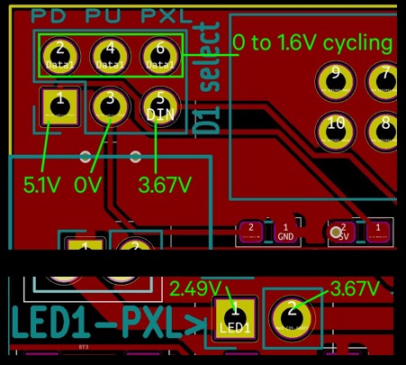
With all D1 jumpers removed, as well as the LED1-PXL jumper:
I get 0V to 1.6V cycling on data1 pads.
There’s 5V on the “PD” pad.
There’s 0V on the “PU” pad.
There’s 3.67V on the “PXL” pad.
The only place I find 2.49V is on the board side off the LED1-PXL jumper.
The pixel side of that jumper carries the same 3.67V from the D1 pin, through
the 330 \Omega data resistor, and through all the onboard pixels data pins.
Why do I get the feeling there shouldn’t be 3.67 running through the onboard pixels?
I reflowed them just now but same results. I suppose I could remove them…
But no shorts across pixel pins, and when hooked back up and assigned a blade style, they work correctly.

I’m including 1 screenshot illustrating this potentially vague info.
Screen Shot 2022-06-14 at 6.33.09 PM

I’m thinking that the script must be operating D1 in some weird way.
I think I need to try it on my side and see if I get the same problem.
Can you post the config file you’re using?

Should I put the PR together and do it that way?
THere’s some read-me stuff at the top of the script, the config defines and script edits and stuff might make more sense with it viewable all together.

Either way works for me.

1 Like

PR submitted

Ok, I’m a moron.
The reason it measures the voltage weird is because the voltage is weird.
The voltage is weird because there is a LED pulling power on the breakout board. Doh!

Anyways, I cleaned up your PR and removed a bunch of stuff that isn’t necessary. Checking an OLED display is generally not needed, because if there is something wrong with i2c, then motion won’t work.

Checking motion explicitly is also generally not necessary as the searial monitor will be full of “motion timeout” messages if motion doesn’t work.

I remove spAUXILIARY, because I couldn’t understand it. I replaced it with spA spU spX instead.

Will #define ENABLE_SERIAL be needed then to use OpenOCD or ST-link utility?

No, OpenOCD doesn’t use the serial port. It uses the SWDIO/SWDCLK pins to talk to the built-in debugger hardware on the chip. When testing, all that is required is that OpenCD can see that the chip is there, that is enough to tell you that the pins are working and not shorted to anything.

1 Like