This was the diagram I initially used to get Blade ID working in a thin neck saber. This setup didn’t monitor Blade ID constantly though, and adding that second resistor in the emitter can be a little tricky depending on the hilt and chassis. It was said this setup simply helped differentiate between different states with help of Blade ID and resistors.
I think it kind of mimicks what SnapshotBladeID was supposed to do?
For Proffie V3 though, I don’t think this method would be even necessary 
With the pullup (or the V3) AND proper resistors everywhere (in the blade and in the grenade section.) I think it should be easy to make a parallel configuration work, and it would be able to tell if the grenade section is connected or not. Of course, you’d have to use the formula for parallel resistors to figure out what values the blades would actually generate:
blade id value = \frac{1}{\frac{1}{grenade id resistor} + \frac{1}{blade id resistor}}
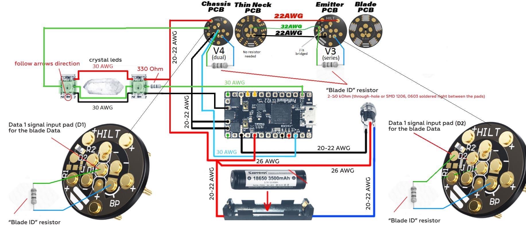
This circuit diagram is misleading.
- You have a blade ID resistor in the hilt section, get rid of that.
- Blade IDs shouldn’t connect to the BP (blade detect) pin. (Unless you short BP to -, then it’s fine.)
- It doesn’t show a blade ID resistor in the blade.
- The blade ID resistor in the thin neck section can go either on the “thin neck pcb” or on the “emitter pcb”, or anywhere in between. (Between the black and the green wire.)
It’s probably easiest if the resistor in the thin-neck section is significantly larger than the ones in the blade. Like maybe use a ~47k in the thin-neck section and a ~4.7k in the blade.
@profezzorn there’s something I don’t understand. If I follow the wiring diagram, on the first PCB he lacks a second data pin. And he puts the second PCB in a series config. This would negate any connection to the actual blade, since the Data would just be repeated by the PCB LEDs and thus any blade resistor could not be sensed.
It would work if he put the second PCB in mirror mode (V2, I think) or if he changed the first PCB to a rotary connector with extra pins.
I see. I won’t be using that diagram again in any case. A hilt-side Blade ID resistor was seen in the Proffieboard manual, but perhaps it needs to be phased out from the manual?
So to sum up all this info and see if I understood it correctly:
- To have different “states” (blades, control of all LEDs) in thin neck hilts, I’d need a Blade ID resistor in the grenade and in all my blades (with different values per blade, say ~4.7K and ~6.8K)
- For standard hilts, only a Blade ID resistor in the blade would suffice
- For 1 and 2, I can calculate the ID and resistor values with the formula stated above. But ~47K for the grenade/thin-neck section and ~4.7K (or another value for another blade) would be good
- No SnapshotBladeID would be needed for this method
- Will the Proffie V3 have constant Blade ID monitoring as a default? According to the POD, I need to use #define BLADE_ID_SCAN_MILLIS 1000 and
#define BLADE_ID_TIMES 10. But will I also need a #define BLADE_ID_CLASS and #define SHARED_POWER_PINS? And would this be the same for the Proffie V2?
I think I’ll be needing some new blades if yes to 1. If it can give me the features I was looking for, then it’ll be worth it.
It was a while ago, but I wired my hilt exactly as the wiring diagram said I should. Through the Serial Monitor and scanid I was able to detect 3 “states”:
- Chassis-only
- Chassis inserted
- Blade inserted
All had different scanid values. The only problem was that the ProffieOS couldn’t instantaneously switch between the 3 states without flipping the kill switch ON or OFF. Someone in the Proffieboard Support Group on Facebook came up with this method and it “worked” for him. I have no clue how it managed to work though.
The problem is that per default, ProffieOS only reads the BladeID at startup or if a Blade Present pin is short. But now with ProffieOS 7, you don’t need it, you just enable constant monitoring. Incidentally, we have been testing and #define BLADE_ID_TIMES 10 is not really needed. Unless your Blade ID values have so much noise that the values overlap.
PD: you should really consider using a rotary connector on the grenade.
The Shtok’s Rotary Connector is excellent, but may be overkill.
The Battery and Speaker should work, too. Just use the speaker pins for Data1 and Data2.
- And with these resistors, you can also see if a chassis is inserted or not, correct?
- Yeah, that would be the first thing I’d normally do
- Cool, good to know constant monitoring can be enabled from ProffieOS7
Using the Rotary connector or Battery/Speaker connectors would be the easiest way to do it. But I’ve been looking for a way to make it work with the NPXL connectors, as I’d like to have some LEDs on top of a chassis. So if all I have to do is add a few resistors to make BladeID work, then I’m willing to try it. Worst case, I’ll just settle for a the non-LED connectors and save the blinkies for the emitter LEDs.
Besides, my current blades have been sanded too much, so it’s a good excuse to build some new ones.
Only needed if you want to have different settings for “thin neck section connected” and “thin neck section” not connected.
Seeing differences between blades without resistors may still work, but there is absolutely no gurantee. You’ll have to try it to see if works.
No, at least not for now, constant blade ID monitoring is a configuration option.
BLADE_ID_CLASS is only needed if you want something other than the default. For a V2 board, I would recommend adding a pullup resistor and then use that blade ID class instead, since it is more reliable, for a V3, the default should be fine.
This is generally always needed when running constant blade id scanning, because the power pins are shared by the WS2811 blade class and the scanning code.
This one might not be needed unless you see problems with your readings.
I see. Well, I guess I can build one new blade with a Blade ID resistor and see if my current blade without resistor can be distinguished. I don’t know how different the values will be between those 16 LEDs on the Shtok V3 connectors and that non-resistored blade though… We’ll see.
Either way, I think I understand it all much better now. Thanks for all the info and clarifications, I learned a lot today!